Biquinary counting is another way to represent decimal (base-10) digits using a pair of binary (base-2) and quinary (base-5) digits. BCD counters like the 74LS90 separate out the mod-2 and mod-5 counters to allow the user to wire the counter in output modes of binary-coded-decimal counter (typical) or biquinary-coded-decimal (amongst others).
#todo add video of biquinary counter leds
biquinary : of, based on, being, or relating to a mixed-base system of numbers in which each decimal digit n is represented as a pair of digits xy where n = 5 x + y and x is written in base 2 (binary) as 0 or 1 and y is written in base 5 (quinary) as 0, 1, 2, 3, or 4.
In digital electronics, this manifests as a count-to-5 3-bit counter with a 4th top bit toggling every 5th count (so two cycles of 5 counts). This can also be thought of as a decade counter. See the second heading below for the state table.
| Note in digital electronics we represent the quinary (base-5) digit as a 3-bit value from 000 to 100. In other cases the full 5 digits are used.
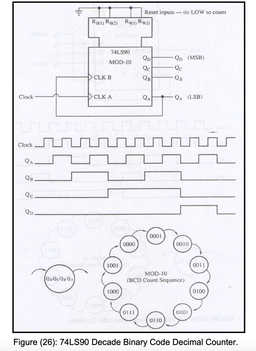
Standard Decade Counter with a 74LS90
When using the 74LS90 BCD decade counter for the first time I was wondering why they had two separate counters in side, a mod-2 counter and a mod-5 counter.
The common way to configure the 74LS90 as a BCD 4-bit decade counter is as follows (source)- CLK A is the mod-2 counter input and CLK B is the mod-5 counter input:
 By connecting,
 Q_A, the output of the mod-2 counter (1-bit output that toggles every two cycles) to, CLK_B, the input of the mod-5 counter (3 bit output that counts up to 5), we create a mod-10 (decade) counter.
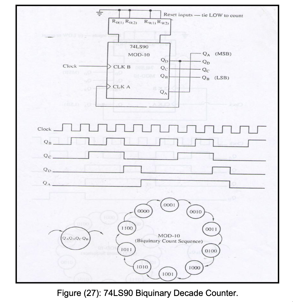
Biquinary Counter
But we can also create a biquinary counter, where for the 4 bit output the bottom 3 bits have two cycles of incrementing from 000...100, and the MSB is 0 for the first 5 sub-cycles, and 1 for the last 5. A timing and state diagram explains it better:
 Note clocks are falling edge triggered. The way to setup the biquinary counter is to have the main clock input into
 CLK B (the mod-5 counter) and have the Q_D output (MSB of the mod-5 counter) as the input to CLK A. This means when the mod-5 MSB goes from 1→0 (on the 5th count) the mod-2 counter will toggle. Note that the biquinary outputs must be taken as shown, with Q_A as the MSB and Q_B as the LSB.
Usefulness
The top bit can be thought of as a checksum .This way of counting is actually used in the Japanese abacus counting system. It seems it is also used in one of the worlds oldest existing working computers [hackaday], but there it is implemented with 7 relays for 7 digits, instead of the 4 bits above.
#todo add photo of abacus
#todo add project link