When messing around with a blues.io notecard and an external GPS antenna, I was getting 0/0 SNR db ratio on the readout from the card.location request. Obviously it means my antenna isn’t connected, or something is wrong at the hardware level.
The fact was I had attached an active antenna and hadn’t set up the notecard to provide the DC bias that the active antenna needs.
The Notecard design allows the option of a passive or active GPS antenna, and can supply a 3.3V - 4.0V bias voltage to power an active antenna’s LNA. If an active antenna requires a different voltage, the board designer can inject whatever voltage they require into the antenna’s coax by feeding it to the
VACT_GPS_INpin. (via docs)
But note, for the boards that already include an amplification stage directly from the antenna, called a Low Noise Amplifier (LNA), the docs state that an active antenna cannot be used. This is likely because they have no way to bypass the on-board LNA, and the resulting doubly-amplified signal would clip above what’s expected, or worse, damage other parts of the board.
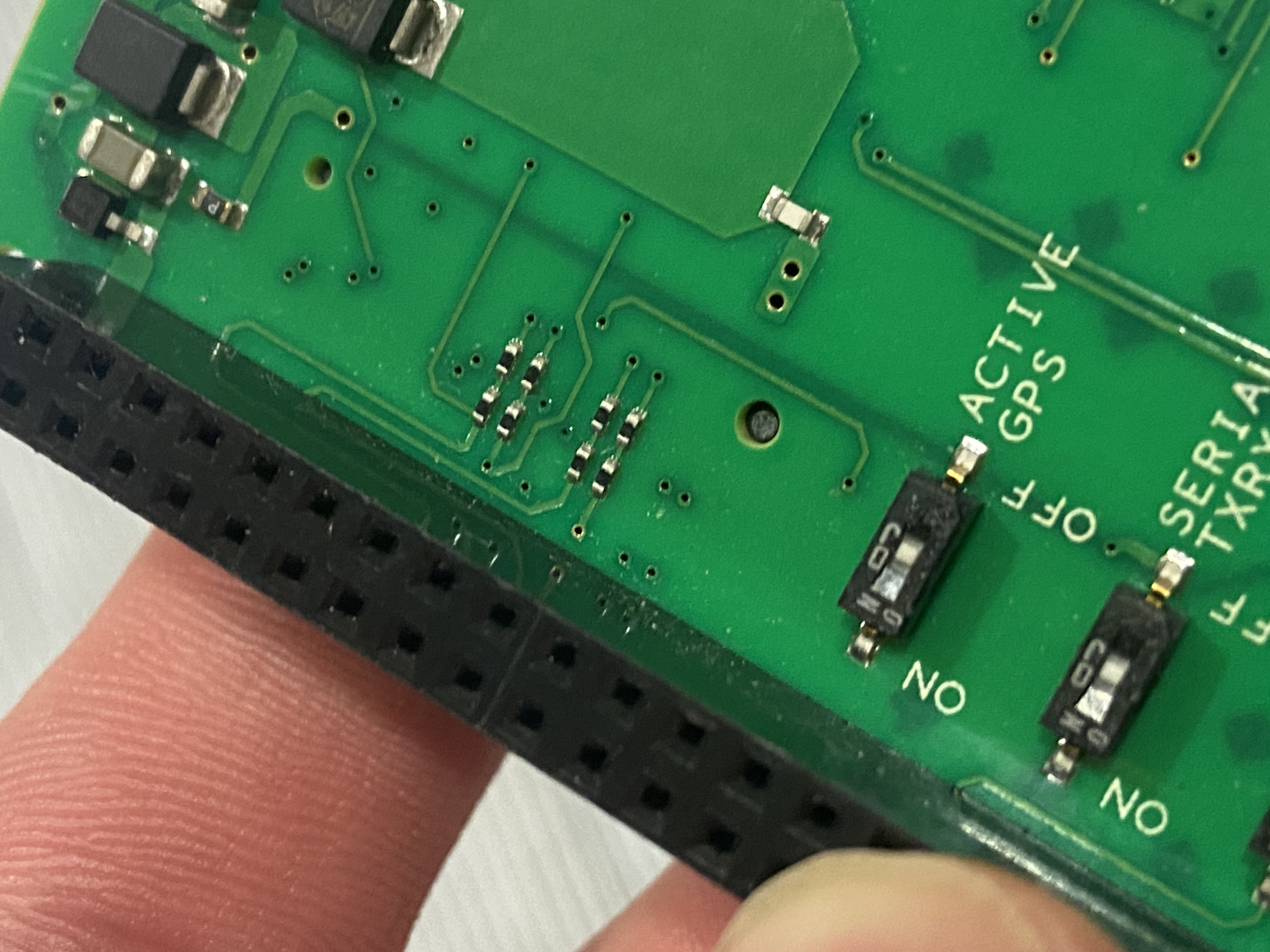
So at least for Blues.io devices, notecarriers/notecards with an onboard LNA cannot use an active antenna, and for the ones without the onboard LNA we can toggle the the Active GPS DIP switch.
Showing the active GPS switch on the Notecarrier Pi
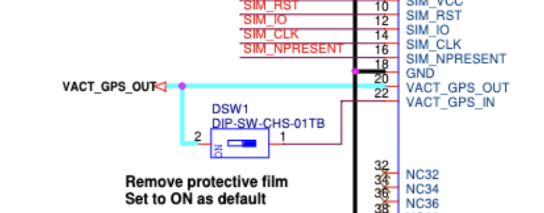
Schematic - the VACT_GPS_OUT line will be connected to the coax middle pin, proving a DC bias for the active antenna LNA.
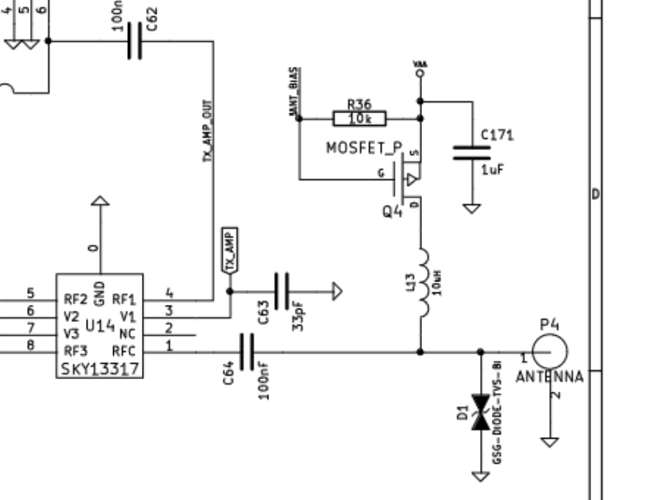
From the hackRF front end, we can see a 100nF DC blocking cap and a biasing circuit. The biasing circuit is to provide the DC bias to the active antenna (with control by the MCU) and then the capacitor removes this bias for the rest of the RF front end.
https://github.com/rad1o/hardware/blob/master/datasheets/else/hackrf-one-schematic.pdf