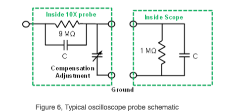
Inside oscilloscope probes there is a variable capacitor to compensate for the unknown capacitance of the scope’s front end. We want to match this with our probe so that we get a flat response over the whole bandwidth of both devices (both the probes and the oscilloscope). The mismatch can be seen as under or overshoot when probing a square wave, but interestingly in the frequency domain we can show that the mismatch results in improper cancellation of the pole and the zero created by the two RC filters.
 Above: Inside a 10:1 probe. Source
The trick is to get . There is actually always zero at (the pole is a bit more complicated).
When then something like the following happens:
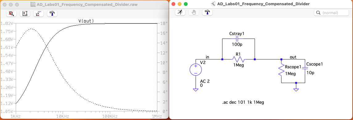
In this case the zero from happens to be at lower frequencies than the pole, thus dominating the gain vs. magnitude plot at lower frequencies resulting in an increasing slope until the pole comes in to flatten things out.
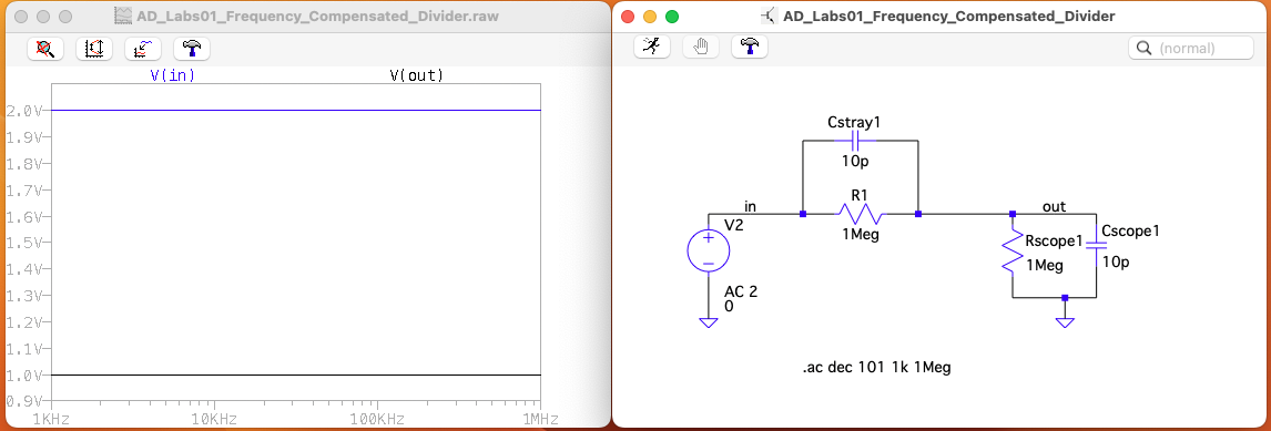
When the pole and zeros exactly cancel, the response is flat: